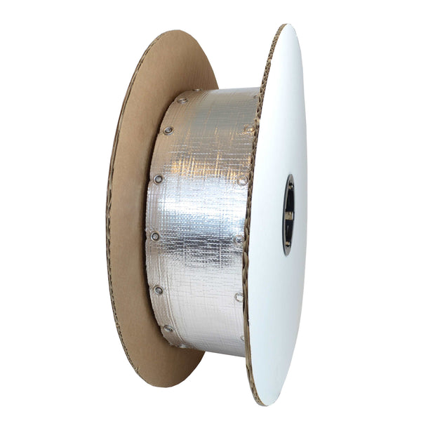
How to Inspect Zippertubing Products
We explain how to make the proper measurements to ensure your product is what you expected.
All Zippertubing® Company tubular jacket products have finished dimensional tolerances as shown in Table 1. All tolerances are specified on the individual Zippertubing® engineering drawings and reference the Zippertubing® standard tolerance drawing: ZT93-98-004. Table 1. Zippertubing® Standard Tolerances (per ZT93-98-004) (All dimensions are in inches)
| Jacket Diameters | Jacket Lengths | ||
|---|---|---|---|
| ZT Size | Tolerance | Length | Tolerance |
| 0 to 3-7/8 | +1/8, -0 | 0 to 24 | +1/8, -0 |
| 4.0 to 7-7/8 | +1/4, -0 | 25 to 48 | +1/4, -0 |
| 8.0 to 11-7/8 | +3/8, -0 | 49 to 72 | +3/8, -0 |
| > 12.0 | Quote | 73 to 120 | +1/2, -0 |
| 121 to 180 | +1.0, -0 | ||
| 181 to 360 | +2.0, -0 | ||
| 361 to 600 | +3.0, -0 | ||
| 601 to 1200 | +6.0, -0 | ||
| >1200 | Quote | ||
Customer Receiving Measurements
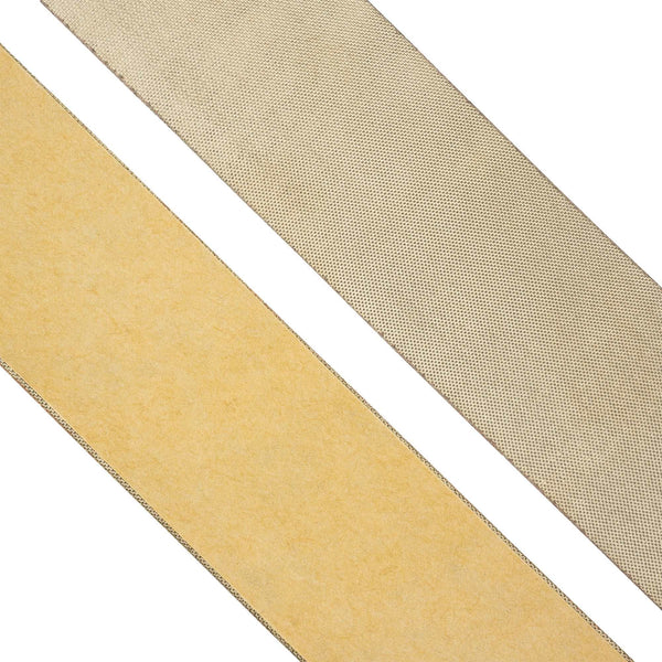
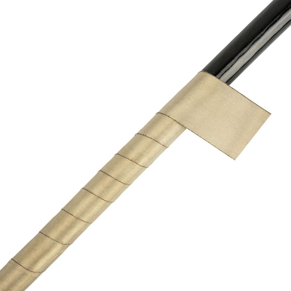
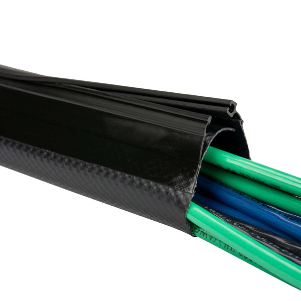
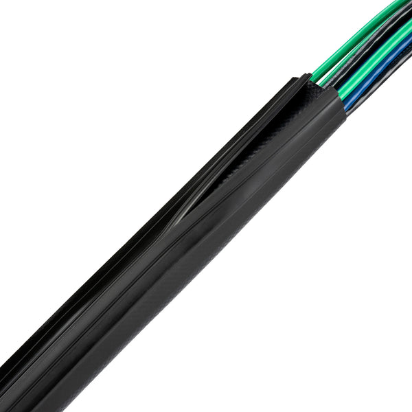
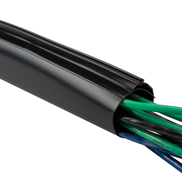
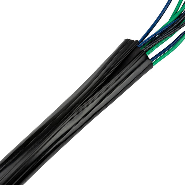
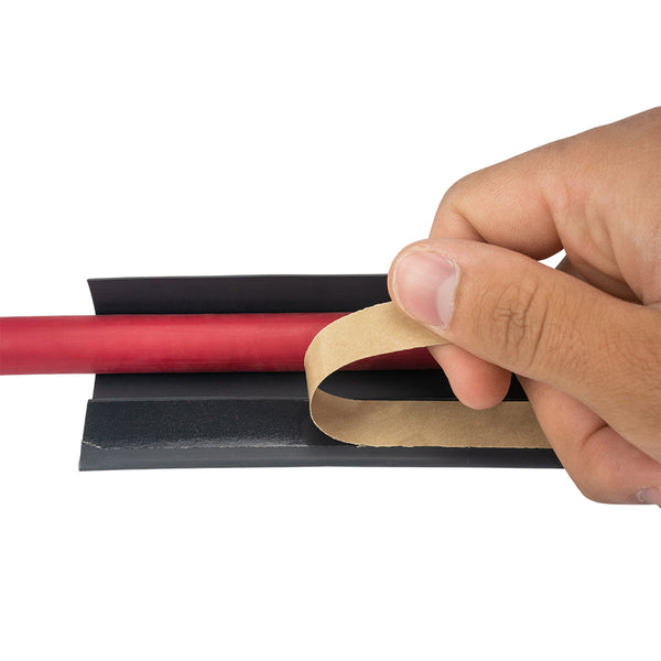
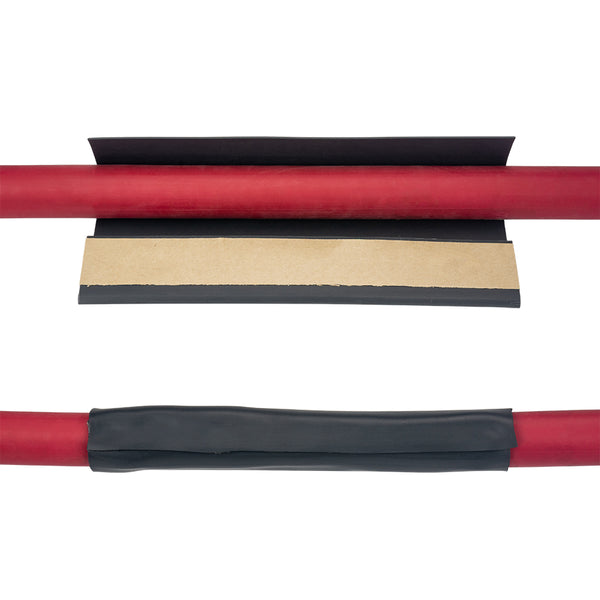
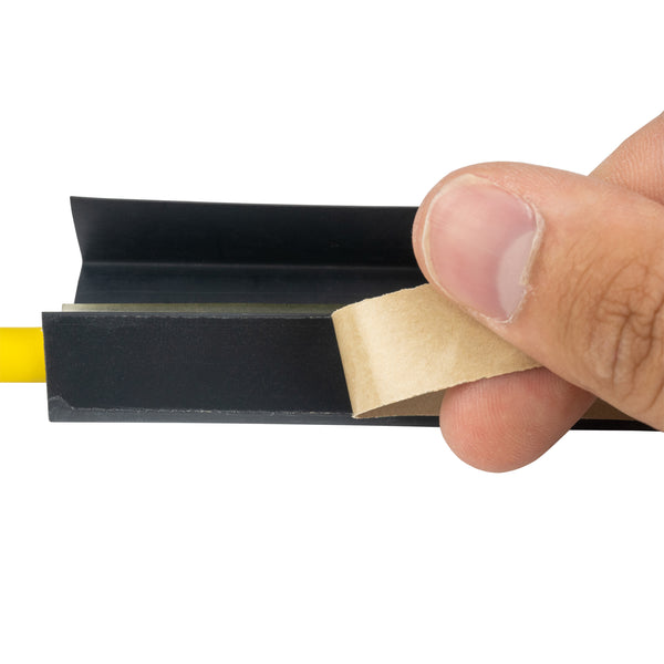
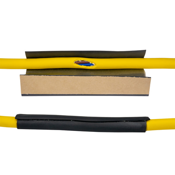
A: Correct Measuring Method All Zippertubing® parts are to be inspected and measured for correct size (i.e. inside diameter) using the “Go - No Go” plug gauge technique with the product in the “zipped closed” condition. For example, based on the information listed in the Table 1, a typical round part with a 1.0” size would be acceptable as long as a 1.0” diameter plug gauge will slide in. 1-1/8” gauge may slide in but, it should be a snug fit and a gauge larger than 1-1/8” should not slide in. If a part is found to be slightly larger than the +1/8” tolerance limit, confirm that the part size on the shipping tag matches what was ordered on the P.O. and then contact Zippertubing® to be sure the correct part was ordered. If the part is slightly too large, it is still usable. The general rule with Zippertubing® products is that “too large may be undesirable, but too small is scrap!” It is critical to always measure Zippertubing® in the fashion outline above because there are a number of design variables that can cause the lay-flat dimensions to vary widely (from construction to construction) even when the size (I.D.’s) are listed as the same. A few features that can affect the lay-flat dimensions of similar sized parts are round cable versus flat cable designs, internal or external overlap flaps, the type of closure mechanism incorporated (i.e. Tracks, Adhesive, Velcro, Zippers, Snaps, etc.), the jacket material wall thickness and the type of EMI shielding (if present).
B: Incorrect Measuring Method “Never measure the edge to edge width dimensions when performing receiving inspection on Zippertubing® products!” Doing so may yield inaccurate results. The following two examples illustrates why attempting to measure Zippertubing® in a lay-flat condition will most likely yield inaccurate results and may cause rejection of parts that are indeed acceptable. Measuring Zippertubing® parts or indicating a Zippertubing® part width dimension on an engineering drawing in the lay-flat condition is extremely risky because it requires a high level of understanding as to how the product is sized and manufactured. All Zippertubing® engineering drawings define part size (inside diameter or inside width) in the closed condition and specify the tolerance limits shown in Table 1. All lay flat dimensions are defined as “reference only dimensions” and are not to be inspected! It is not uncommon for a customer’s engineering department not to fully understand all the subtleties that could cause a correctly sized part to be rejected by the Q/A department. The following examples illustrate the difficulty and numerous pitfalls that exist if Q/A tries to inspect a part in the lay-flat condition.
Example 1.
Examine Figures 1, 2 and 3. Note that all represent parts with a 1.0” size inside dimension for a finished Zippertubing® part. Also, note the differences in the lay-flat dimensions of the three parts.
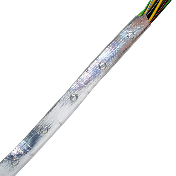
If you were to try and measure the Zippertubing® in the lay-flat condition you would have to determine which dimension is to be measured and if that dimension truly correlates to the cable dimension. Generally, the critical dimension to be measured is the “bead-to-bead” (B-B). The B-B dimension is the centerline of one side of the mechanical closure mechanism to the centerline of the opposite half of the closure mechanism. The two halves of the closure mechanism may or may not look similar to one another. (Figure 1.)

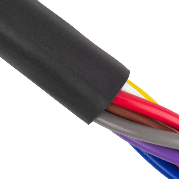
Figure 1: 1.0” Round Zip-On (no shield)
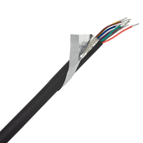
Note: This dimension may or may not be the total part lay flat width. It will depend on whether the part has an internal, external or no overlap flap! Also note that there is a significant difference in lay flat dimensions between a part intended for round cable versus one intended for a flat cable. (Figures 1& 2)

Figure 2: 1.0” Flat Zip-On (no shield)
If we apply the tolerance limit from Table 1 of +1/8, -0.0 inches the maximum acceptable tolerance limit would be approximately 3.53 inches. This is because the tolerance limits are also based on diameter and must be multiplied by Pi to determine a maximum lay flat dimension. The result is that this simple 1.0 inch part could theoretically have a lay flat dimensional variation of from 3.14 to 3.53 inches. Any measurement within that range would be considered acceptable. Although this range appears very wide by standard engineering practices it is within the Zippertubing® acceptance limits indicated by Table 1. The mathematical calculations may seem fairly straightforward, but keep in mind this example reflects the simplest of the Zippertubing® part designs. Measuring lay-flat dimension also demands that the inspector know if the part is for a round, flat or rectangular cable! The Zippertubing® part numbering system is a “blind” system and the part number alone does not tell you this information directly.
If we apply the tolerance limit from Table 1 of +1/8, -0.0 inches the maximum acceptable tolerance limit would be approximately 3.53 inches. This is because the tolerance limits are also based on diameter and must be multiplied by Pi to determine a maximum lay flat dimension. The result is that this simple 1.0 inch part could theoretically have a lay flat dimensional variation of from 3.14 to 3.53 inches. Any measurement within that range would be considered acceptable. Although this range appears very wide by standard engineering practices it is within the Zippertubing® acceptance limits indicated by Table 1. The mathematical calculations may seem fairly straightforward, but keep in mind this example reflects the simplest of the Zippertubing® part designs. Measuring lay-flat dimension also demands that the inspector know if the part is for a round, flat or rectangular cable! The Zippertubing® part numbering system is a “blind” system and the part number alone does not tell you this information directly.
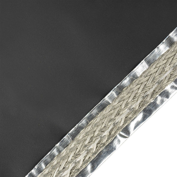
Example 2.
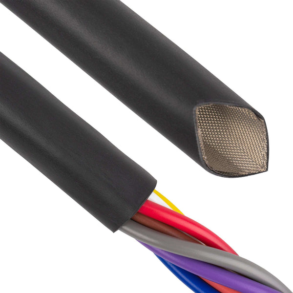
Imagine a 1.0 inch round diameter part that has a .030 inch thick EMI shielding mesh inside of a .040 inch thick outer jacket material (Figure 3). Because this product is an EMI shielded part, it will have an inside overlap flap that is approximately 3/4 inches long and will wrap approximately 1/4 of the way around the inside circumference of the closed tube.

Figure 3: 1.0” Round Zipper-Mesh (with EMI Shield)
What would be the B-B minimum and maximum dimensions? (Figure 3)
The B-B lay flat width will be far larger than the example shown by Figure 1 even though the closed inside diameter dimensions are the same. This is because the total wall thickness is approximately .070 inches and approximately .100 inches for 1/4 of the circumference due to the internal shielding overlap flap condition. You cannot simply measure the B-B and multiply by Pi as in example 1 because it would yield a dimension that indicates the part is for a 1-1/2 inch diameter cable. This extreme variation in B-B dimensions is due to the wall thickness and internal overlap flap. Yet the part is indeed for a 1.0 inch diameter cable bundle. Attempting to make a lay flat calculation accounting for the wall thickness and overlap area has a very large potential for a mathematical calculation error.
CAUTION: If a customer chooses to measure actual part lots and develop lay-flat tolerance values, understand that even spooling and de-spooling process (i.e. packaging) can introduce some dimensional variations. Knitted wire mesh shielding is known to bunch and gather to some degree during the spooling process. When de-spooIed it may be necessary to stretch the material to eliminate this gathering effect and return the part to its actual finished length.
The Bottom Line
- Always, always, always instruct your Q/A department to perform receiving inspection measurements on Zippertubing® parts in the closed condition using only the Go – No Go plug gauge method!
- If your Q/A department rejects materials back to Zippertubing® for an out of tolerance condition and it is found to be within the standard plug gauge tolerance limits defined in Table 1, you will be charged for all freight costs plus a handling and inspection fee.
- If you have any questions regarding any of these dimension and tolerance issues please direct them to the Zippertubing® engineering department.